A discourse on intermodulation noise. V1.0
A discourse on intermodulation noise. V1.0
This paper is concerned with a specific type of intermodulation noise where the noise around an RF carrier frequency is brought down into the video band when a square law detector is used. This is not always a problem because the additional noise is small compared to the signal amplitude. However, with CW immune systems, the DC component of a signal is subtracted leaving the additional noise to degrade the sensitivity of the circuit.
First some terms and notations we will be using:

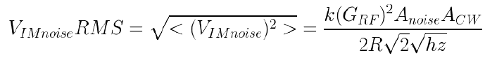
here the ω tilde variable represents a spectrum of frequencies with random phase ϕ tilde. The random phase is important to note in the case of adding noise sources, which results in the amplitudes adding in quadrature. The RMS noise voltage over a bandwidth ω₁ to ω₂ is then:
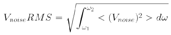
Where the expectation value operator brackets indicate a time average. Because the noise power is flat in frequency the integral is trivial to calculate.
At room temperature, the thermal noise floor is approximately -174 dBm/Hz, or with a
20 MHz bandwidth it is -101 dBm. Later we will have a discussion about other sources of noise in the lab or in application which raise the noise floor further.
We should note at this point that the time average of a sin² or cos² is:

Here we define TSS as:

Some people substitute out the constant 2√2 for 2.8 or 2.5 in their specifications. Historically the factor there represents how much greater the signal has to be than the noise to have a certain low false alarm rate.
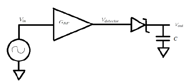
Figure 1
Figure 1 omits the standard inductor to ground and impedance matching networks, the possible bias of the diode etc, as they are not relevant to this discussion. For this case we will assume that the capacitor C is properly chosen so that signals much greater than 20 MHz are averaged, giving the detector a video bandwidth of 20 MHz.
While the detector input power is low enough that the diode is operating in the square law region, the output is:

Where R is taken to be the 50 Ohm terminations generally in this discussion.
Without considering intermodulation noise, the detector output noise is typically dominated by the shot noise in the detector diode. There is some variation in this noise vs signal depending on detector bias, impedance matching networks etc. For simplicity here let's consider a detector that has a 20 MHz bandwidth RMS voltage equivalent to the detector output voltage with an input of -48 dBm, resulting in a TSS of about -45 dBm.
With only a CW input, we have:


and the voltage at the output of the square law detector (at least for input powers where the detector diode operates in square law) is:

which can be expanded into:
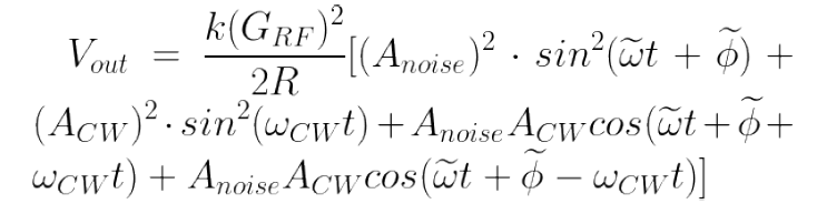
So the remaining noise is:
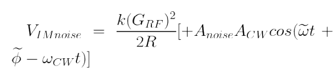
So, the noise in the band from ωcw to ωcw+20MHz will be brought down into the frequency range of 0 to 20 MHz. This frequency difference term, which comes from the cross term in the detectors square operation, is the fundamental source of intermodulation noise.
In order to calculate a new TSS for signals in the presence of this CW induced IM noise, consider:
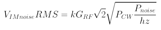
After substituting the amplitudes and amplitude gain for power and power gain:
Now using our previous definitions of the output of the detector for a new signal PTSS and of TSS:
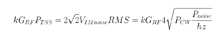
Solving for PTSS:

and expressing the powers in dB, we finally arrive at:

So, if we have a true 50 Ohm resistor noise floor of -101 dBm for a 20 MHz bandwidth, and a CW level of -30 dBm, our lowest possible TSS without considering the detector shot noise would be: -59.5 dBm.
This may seem trivial because, as we noted earlier, a typical detectors TSS is around -45 dBm due to the diodes shot noise. But, there are a few important things to note here: this minimum TSS is independent of gain. So, if you add gain to a detector to bring the TSS down to -70 dBm, in the presence of high CW powers you can see over 10 dBm of TSS degradation. Also, in many circumstances the actual noise floor is higher than the -174 dBm thermal noise floor. Firstly, the RF gain amp has a noise contribution. RF generators often have broadband noise floors significantly higher, and also the phase noise of the carrier signal manifests as noise in the video. We recommend a thorough consideration of the true noise floor in the presence of CW for our customers actual applications and lab test situations.
Further discussion:
Most square law detectors only operate in square law for a smaller range of input powers than their total usable range. When the input power is greater than the square law region, the detector transfer “rolls” into a linear response. Since there is no square operation while the detector is in the linear region, there is no intermodulation noise. Unfortunately, because the detector response has rolled, there is much less signal in this region despite no change in shot noise leading to a severely degraded TSS regardless. Typical silicon shottkey diode detectors only stay in square law operation for about 35 dBm range above their TSS. There are other detectors that stay in square law at significantly higher powers, which can be either an advantage or disadvantage; exactly when they are a better choice in a given situation is beyond the scope of this paper.