Notes on CW Strippers and Dual Arm DLVA's
Notes on CW Strippers and Dual Arm DLVA's.
Introduction.
Logarithmic amplifiers are non linear and therefore, when there is an input signal and a second signal arrives while the first signal is present, it will not register the same change in the output as it would have, had there been no other input signal. In fact, if the first signal is much stronger than the second signal, the latter may not even be seen, as the effective gain seen by the second signal is far smaller than it would have been were the first signal not present.
As an example, suppose we have a system set to start logging at -40 dBm, and there is -20 dBm CW present at the input. This -20 dBm CW signal will cut the gain of the log amp by a factor of 100. So if a small signal, -40 dBm, comes in while the CW is present, the amplitude of the small signal will be 1% of what it should be, and will be missed completely. Another way of looking at this is to observe that the output difference between two signals applied to a log amp in its logging range, is the ratio of the signals. Therefore, when there is -20 dBm CW present and we add a pulse of -40 dBm on top, the ratio of the two signals changes by 1%. This is too small a change for the logger to see.
Before proceeding with a description of realistic CW strippers, there are 3 general points that need to be addressed.
1. Loss of detector sensitivity.
If the “CW” or unwanted signal is sufficiently large, the detector will begin to roll off, or go out of the square law region. It has lost sensitivity. This decrease in sensitivity at high input power is corrected using linear extension or adjusting log stage currents. However, once the CW is stripped, the log amp behaves as it would when there is no large input present and small pulses only activate the lowest log stages which are set up for a detector which is still in the square law region. As a result, even if the CW immunity system is ideal and provides a perfect canceling level, a small amplitude pulse will not be measured correctly if the CW is large because the pulse seen out of the detector is smaller than it would have been in the absence of CW. If the input pulse is comparable to the CW then it will be measured reasonably accurately and if much larger than the CW it will be measured correctly as it will give essentially the same signal as it would have in the absence of CW.
There is nothing that can be done about regaining the sensitivity in the video!!
2. Inner modulation noise.
In the presence of a CW signal, if the detector is in the square law region there will be excess noise resulting from interference between the CW and the white RF noise. (When squaring the sum of the two amplitudes to get the power, which is what determines the detector output, one gets a cross term, which leads to the familiar sum and difference frequencies. The last term will have a contribution in the video band width, since the noise spectrum is white.)

Note the TSS will be even higher, -39.5 dBm.
The CW power was chosen at -15 dBm because most detectors will go out of square law around this power and the inner modulation noise gets smaller until it has completely vanished once the detector is in the linear region. You will notice that as you increase the CW power, you will start to see the inner modulation noise. Then it will increase as you raise the power, but it will lessen and disappear once you go out of the square law region.
Note that if you were not stripping the CW you would not see this noise, as it is very small compared to -15 dBm. However, it does impose a limitation on how small a pulse you can see with CW present.
3. Effects of RF frequency.
When the RF frequency of the signal that one is trying to detect in the presence of CW is close to the frequency, harmonics, or subharmonics of the CW, interference leads to strange looking outputs. Once again, this cannot be dealt with in the video.
Characterization of CW strippers.
- Droop: Droop is the amount that the pulse drops for the longest pulses desired. The droop is worst for small pulses and should be small enough so that the pulse remains within spec. It is usually enough for the droop to be less than 0.5 dB. Sometimes people spec it at zero but this is ridiculous, unnecessary and impossible to verify. In principle it would require an infinitely accurate scope or meter. The droop results from what is either AC coupling or effective AC coupling.
- Recovery time: This is the maximum time for the unit to return to the the baseline after a pulse that is shorter than the longest desired pulse.
- Attack time: this is the time measured from Tmax for the level to be within Vr of the baseline when CW is being stripped. i.e. It is the minimum time after Tmax that the unit will measure a pulse riding on the CW accurately enough to meet specs.
These are illustrated in Figure 2 below:

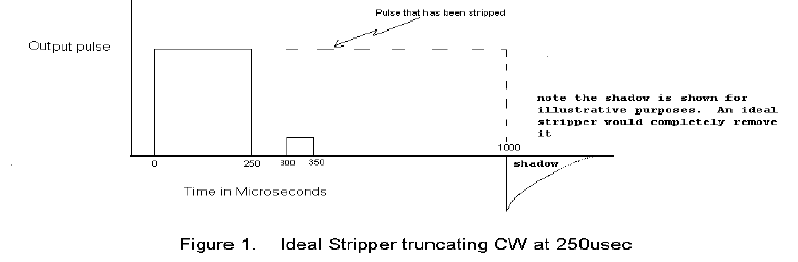
Finally, the shadow time needs to be minimized. This is done by using a diode in series with a small resistor, parallel with the resistor that sets the RC decay time, inserting it so that is reversed biased for positive going pulses and forward biased when the pulse goes negative to give a short RC time constant to remove the negative excursion in a short time.
Basic Restorer Design:
There are many ways to design CW strippers. One simple type is discussed to illustrate the principles. Some of the pitfalls are discussed. In Figure 3 we illustrate a simple design after which we discuss the limitations of this type of stripper.

- The stripper is always taken from the output of the linear amplifiers. If we were to take it from the logarithmic output this would be disadvantageous because the compression would make the stripper less sensitive for large pulses when the large pulses are those that need the maximum restorer strength.
- Care must be taken because gain is being put in a feedback loop so it is easy to get oscillations unless the loop is slowed down sufficiently.
- The gain of the amplifiers in the feedback loop must be sufficient to null the output of A3 sufficiently. (<8 mV offset for the L-17D with a 1 dB error permitted for signals on CW) . If we assume that A1 Is running at a gain of 8 so that the total gain to A3 is 512, this gain would set the start of logging at about 50 μV. So, if we want to strip 3 decades (30 dBm), and we assume there is no roll-off on the detector, we have to match a 50 mV input. Thus if we permitted a max offset of 8 mV at A3, the gain in the amplifiers S1 and S2 needs to be 50/8 , or about 6.25. Is it better to put the gain in S1 or S2? Putting gain in S2 often adds noise to the signal but putting too much gain in S1 causes it to limit early and, as explained below, this increases the attack time for large pulses. The choice of amplifiers thus impacts this decision.
- The time constant is not simply RC because of the gains in the loop. If no amplifier has limited, then the time constant is given by RC/G where G=the product of the gains of all the amplifiers. Therefore if we were to use a gain of 10 in the feedback loop G= 5,120. If we needed a time constant of 1 ms to have acceptable droop, RC needs to be roughly 5 seconds! For bigger pulses where S1 limits, one has to calculate more carefully. The capacitor will be charging with a current equal to Vₗᵢₘ/R until it stops limiting and then the RC time constant will dictate the charging. This will lead to attack times far longer than those given by using the time calculated using the RC time constant.
- The choice of capacitor types is very important as capacitors seem to have a memory.* If one builds an RC circuit and puts it into a log amp, one would expect it to produce a straight line output until the lower limit of the logarithmic response is reached. In practice this does not happen and there is a tail which can last several ms. For typical surface mount caps they will start to diverge from an exponential decay at about 50 dBv below the full charge. The origin of this effect is not understood by, or even known about, by most capacitor manufacturers. Polypropylene caps are the best and are good to about 80 dBv. Unfortunately they are very large. 3D silicon capacitors made by IPDIA are the best surface mount capacitors we have found.
- If you get oscillation, the first thing to check is that the resistor in series with the diode is large enough. If it is too small then the feedback will cause oscillations.
*This is too small to notice on a scope with a linear amplifier.
The stripper shown will have a very long attack time and there are several methods of overcoming this. Some people use hierarchical loops, with restorers around each amplifier. These can be difficult to use because of multiple time constants which can easily induce ringing. Anadyne has a variety of restorer designs which we intend to produce as products, and their capabilities will be discussed at the end of the note. These are proprietary, so we will not discuss them here.
We would like to emphasize that there is nothing that a restorer can do to regain the sensitivity of the detector, in the presence of high levels of CW. For single detector units, we recommend that you use a Schottky detector and minimize its roll-off by connecting a resistor to the output of the detector to load the detector, Many detector manufacturers show curves of the response vs load which should provide guidance in the choice of load resistors.
Dual Arm DLVA's with CW strippers.
For the fundamentals on dual arm DLVA's see the L-17C application notes.
Most dual arm detectors have a range of 70-80 dBm. Since a single L-17D is capable of handling up to 60 dB of range, there is plenty of latitude regarding where to put the crossover, i.e. go from one detector to the other. However, the key issue to remember is the following:
No matter where you put the crossover, the detector on the most sensitive arm is the one that has to see small pulses, and it could be hit with CW that is very high powered.
Suppose you want to strip CW up to a power Pₛ above the start of logging, which we'll say is at Pₒ, and retain sensitivity to pulses that are smaller than those that can be detected by the low sensitivity detector D2. Then you cannot limit the power going to D1, the detector in the high sensitivity arm, below Pₗᵢₘ = Pₛ + Pₒ. If you do, and you have CW Power that is at the limit, even if the CW is stripped, D1 will not be able to detect anything, as it will be in a limited condition. Note that in general a CW stripper is required on each arm. This is because there is CW that affects D2 unless the crossover point is set at a higher power than the maximum power of CW that must be stripped.
At this stage, what the best strategy for deployment of strippers, where to cross over etc, is too complex to discuss here. You have to look at the specifications before you can decide on strategy. Systems designers have to be aware of the tradeoffs. The issues are:
- What kind of accuracy do you want for small pulses in the presence of how much CW? Using a detector that rolls off early has the advantage of not producing as much inner modulation noise because it goes into the linear region earlier. On the other hand, once the detector has rolled of, the smaller pulses are severely affected by the loss of sensitivity of the detector.
- However, if there is too much inner modulation noise, you will not be able to detect the small pulses anyhow.
- Another strategy to consider is to cross over to the less sensitive arm only 15 to 20 dB above the start of logging. Then when the sensitivity of D1 is lost due to excessive CW, you will lose the pulses, or their amplitude will be severely degraded from -70 to -50 dBm (assuming start of logging is at -70 and we have 20 dB of range on the sensitive arm). However, you will then have a perfectly good measurement of pulses greater than -50 dBm if you use a detector that rolls off at high power for D2, for virtually any input CW power. For D2, inner modulation noise is no longer a problem since there is a lot less gain in front of the detector. (Similar to a single detector discussed earlier) Therefore, one can use a detector that rolls off late for D2.
- Finally, one has to consider the issue of attack time if one wants to strip very large levels of CW. It becomes difficult to get a good attack time when very high levels of CW need to be compensated. This problem is more severe in the case of duals for obvious reasons.
It is difficult to discuss these issues in more detail without revealing ANADYNE trade secrets. We suggest that you specify your requirements and ask ANADYNE if we can provide design assistance which will meet those requirements. In this regard please note novel design approaches with which we are familiar are likely to be subject to US export law and regulation.
ANADYNE will be bringing out a line of boards in the near future (for which patents are pending) that will be about 2.5 cm on a side and will contain one or two L-17D's and a restorer system. Each board will be DC balanced by ANADYNE, but will have no detectors. The user will therefore have to package the board, add detectors, and tune the cross over and transfer. We will be announcing detailed specs for models in the near future.
As an example, our best CW stripper, for which patents are pending, can strip 40 dB of CW with an attack time of less than 3 μs for any desired pulse length. It can run 60% duty cycle for pulses less than 300 ns with a 90+% duty cycle capability for pulses longer than 500 ns. We anticipate that these boards will be subject to ITAR regulations.